
How 3D printed intake manifold increases the engine performances
3D printed intake manifold enhances the performance of engine.
The modern Turbo Diesel engines have increased their performances compared with “old” Diesel engines. Unfortunately, new severe requirements regarding their emission have to be faced.
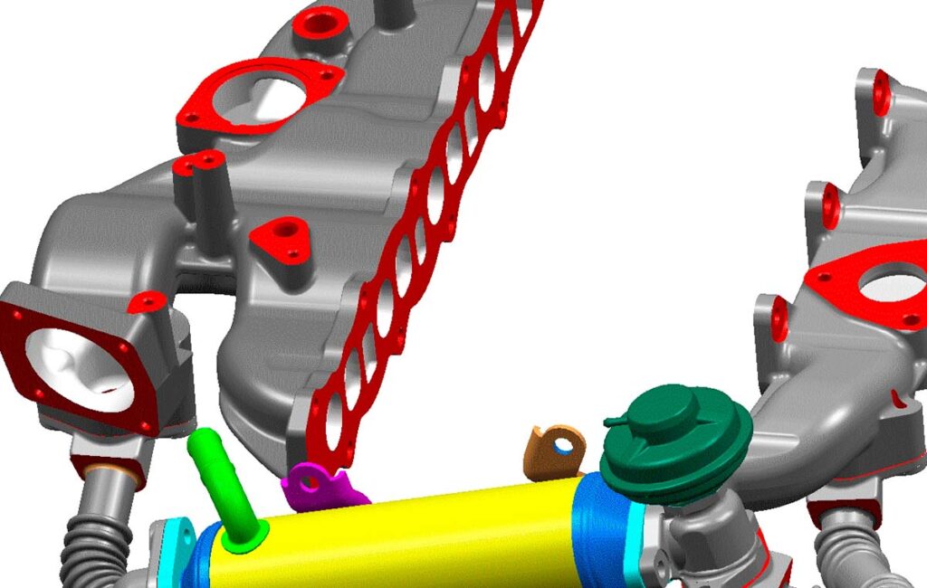
The use of EGR (Exhaust Gas Recirculation) can help engine manufacturers to keep under control the emissions to accomplish to the Euro 4 requirements.
In order to improve EGR system VM Motori S.p.A. (Cento, FE – ITALY) decided to test different alternative intake manifolds. Instead of taking a long projecting and engineering time, VM engineers’ good knowledge of Additive Manufacturing techniques allowed to spend only a few weeks to reach the best performance of the manifold and the engine.
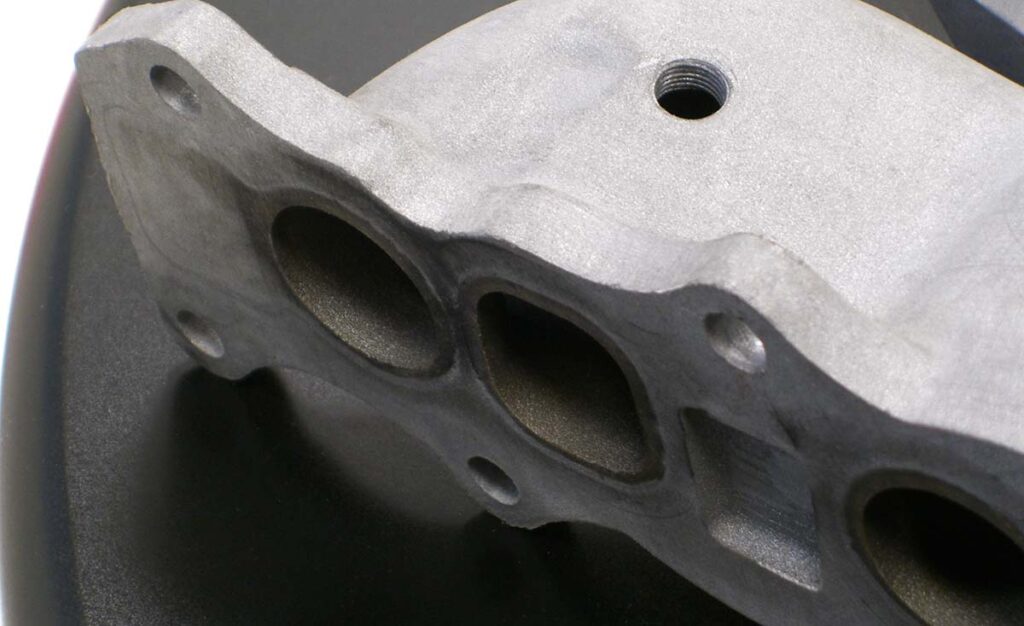
The study was performed using 3 different models, 3D printed by CRP Technology in Windform XT, a Carbon fiber filled material from the Windform range of composites for Laser Sintering systems. Windform XT is now replaced by Windform XT 2.0.
Each prototype was prepared with a typical lead-time of 2/3 days. This kind of “fast-production” was very useful for VM engineers, shortening 10 times or more the standard lead-time for this kind of product.
The 1st model was called “V1”, and it was used for dyno tests without any issues.
Then the VM engineers worked on other two releases, “V2” and “V3”, to optimize the partitioning of EGR on each cylinder, reaching the goal of a maximum of 4% of difference among the 4 cylinders (as a target for Euro 4 emission level).
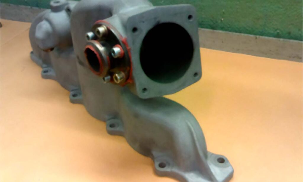
Usually “standard” lead-time for a sand cast aluminium intake manifold is about 2 months. In this case they made 3 different manifolds spending only 6/9 working days. So the engineering phase that usually takes several months, lasted less than 2 weeks.
In the following table we can see some interesting data to give an idea about thermal and mechanical stress, applied to the manifold, during normal engine use (real life engine operating points where the EGR is activated so the intake temperature is increased by mixing fresh air and hot exhaust gases).
Mode | Air Mass kg/h | EGR Rate % | T. Manifold °C | T H2O out °C | T H2O in °C |
|---|---|---|---|---|---|
Average: | 67,37 | 83,56 | 81,29 | ||
1 | 21 | 57,00% | 65,80 | 79,20 | 78,70 |
2 | 56 | 36,00% | 60,70 | 82,90 | 80,90 |
3 | 71 | 44,00% | 60,00 | 81,70 | 80,80 |
4 | 87 | 22,00% | 44,40 | 82,80 | 80,30 |
5 | 94 | 34,00% | 50,40 | 82,60 | 81,30 |
6 | 105 | 20,00% | 49,70 | 83,50 | 80,80 |
7 | 105 | 27,00% | 71,00 | 84,00 | 81,10 |
8 | 115 | 26,00% | 47,20 | 82,60 | 81,30 |
9 | 48 | 49,00% | 73,50 | 82,40 | 80,90 |
10 | 123 | 21,70% | 64,50 | 84,20 | 81,10 |
11 | 95 | 27,50% | 60,30 | 83,60 | 81,10 |
12 | 71 | 34,50% | 73,80 | 83,30 | 80,40 |
13 | 148 | 23,00% | 85,40 | 85,40 | 82,00 |
14 | 176 | 27,00% | 72,70 | 84,80 | 82,30 |
15 | 280 | 19,00% | 91,70 | 87,10 | 83,80 |
16 | 275 | 20,00% | 106,80 | 86,90 | 83,80 |
Mode | Air Mass kg/h | EGR Rate % | T. Manifold °C | Pressure Intake Manifold BAR |
|---|---|---|---|---|
Max. Output 110 KW (150 Cv) @ 4000 Rpm | 550 | 0,00% | 55,00 | 1,50 |
In the tables we can see also some values about H2O temperature, because there’s coolant fluid flowing in a duct beside the manifold, increasing its temperature (because of reduced heat exchange trough the wall) but without affecting its functionality at all.
VM engineers have done several tests, without any kind of problem. The manifold has supported also some tests lasting 2,5 hours, with the engine at the maximum output, and at the end, it was still perfect, ready to be used again.
For the production of the new Turbo Diesel Common Rail 2000 cc engine, designers decided to use aluminium manifolds and when they tested the first engines, they observed exactly the same results of Windform XT manifolds.
It demonstrates how reliable and useful can be a study done in an incredible short time, thanks to Windform XT properties.
Sidebar: the new Chevrolet Captiva will be powered by this engine
From Chevrolet official web-site: “From the manufacturers of the very first SUV back in 1935, Captiva is the latest in a long line of authentic sport utility vehicles offering great value for money in a stylish and practical package. Designed specifically for the European market, it will be available with front or all-wheel drive, five or seven seats and with a 2.4 litre petrol or leading-edge 2.0 litre diesel engine and will appeal to a wide range of customers. Captiva will be on sale in Europe from spring 2006.”
Engine/powertrain:
RA420DH6
Type / 4 cyl/in line, common rail diesel
16 Valves
Displacement / 2,000 cc
Max. output / 110 kW/150 PS at 4,000 rpm
Euro 4